Parametric Design and Pressfit
Before designing my parametric model, I made myself two small test pieces that will give me the ability to quicly see what will be the exact thickness of my pressfit slot in my future designs. I made one for a quarter inches material and one for a 1/8 inches material.
I design the model using Fusion 360 and it was really not hard to design. Here are the sketches:
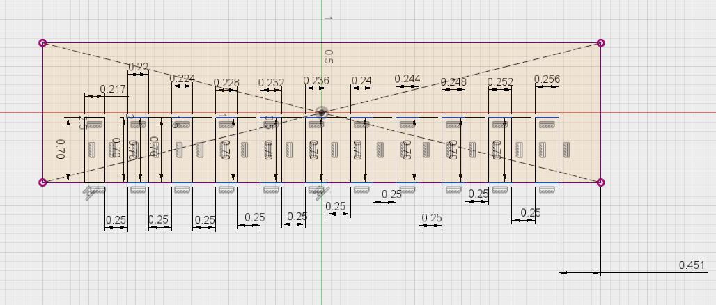
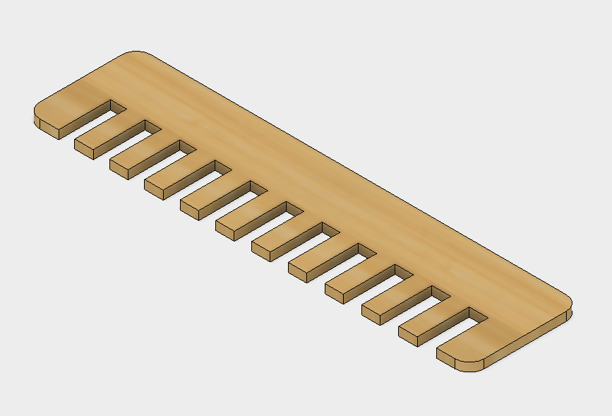
As you can see it's a simple rectangle with slots of differents thickness that have the purpose of testing different materials and sheet of materials to see wich thickness will be a good fit for pressfit. Here is the final model for the quarter inch test
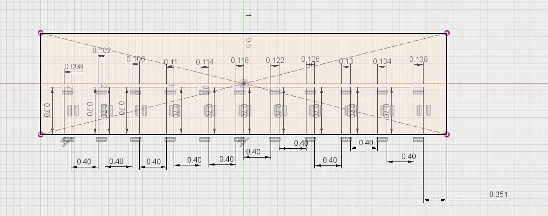
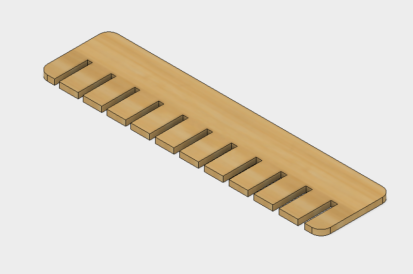
And here is the 1/8 inch model
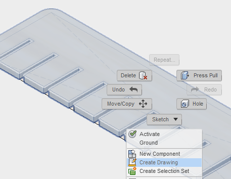
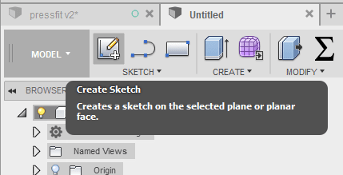
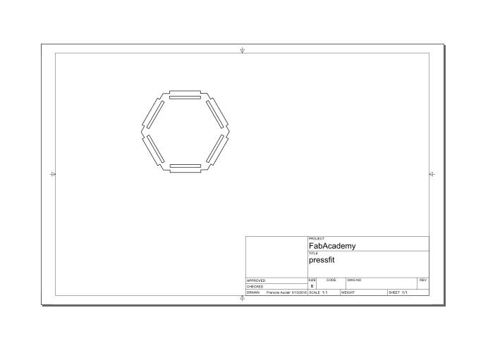
Once this was done I had to lasercut those model, to do so I simple selected the component and made a draw from it using this function:
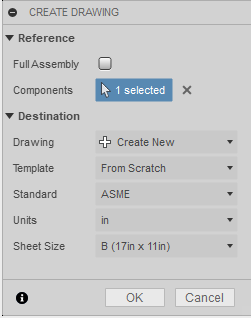
It will then bring you in the drawing interface of Fusion:
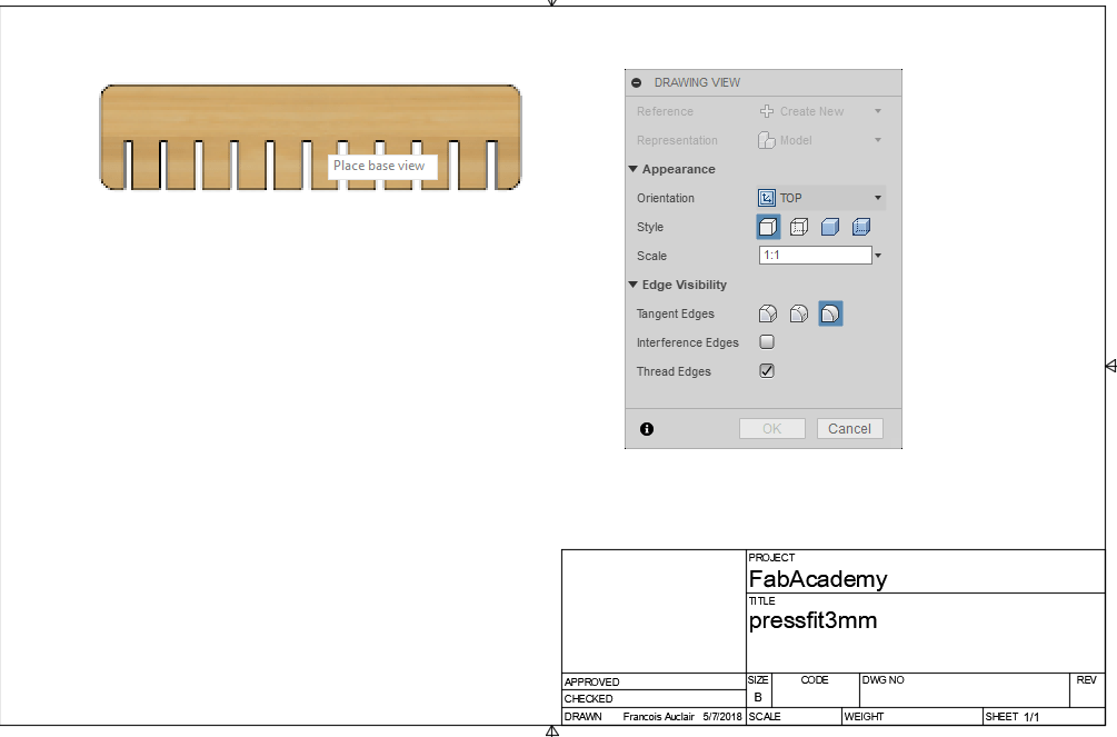
In here you can select multiple option about your draw, first you need to select the orientation, the angle of view of wich you will import you 3d model into a 2d Draw. Also, make sure you use a 1:1 scale or that you remember to correct it once in your third party software, I will use Inkscape.
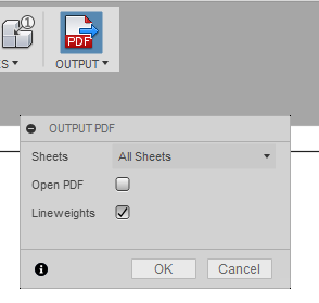
Finally all you have to do is export the whole thing in a PDF format.
Once everything is set up I start the cut and here are the results!
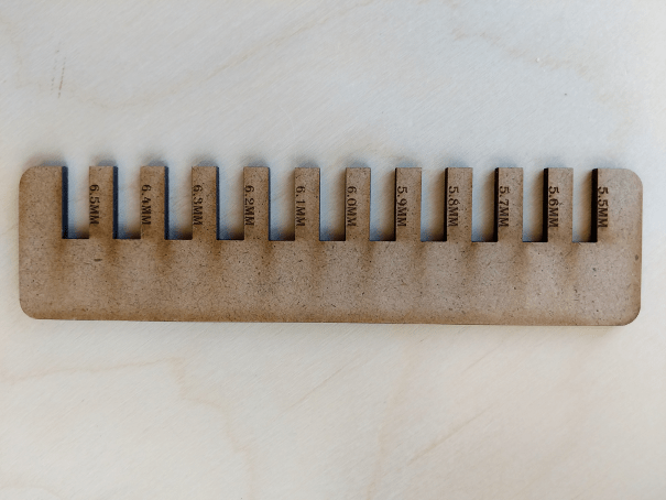
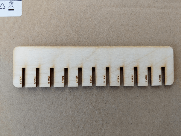
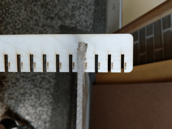
I can now test using this design wich thckness fit better for my pressfit designs. This is a nice little tool that I will use often!.
Parametric Design
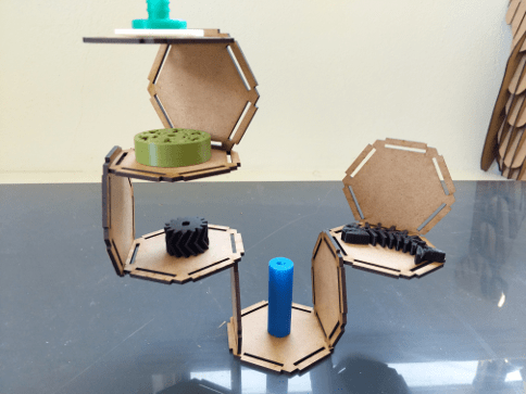
I made my parametric design on Fusion360, It's a simple hexagon that can fit other hexagon inside it, we can then create modular shape using multiple of them. So here is a step by step guide to how I made them.
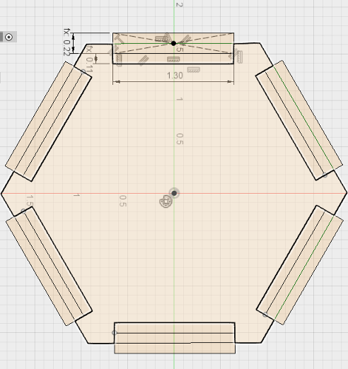
First thing I did was to create a sketch.
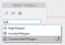
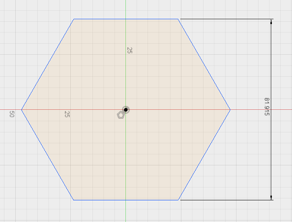
Next, I draw a polygon using the poygon function
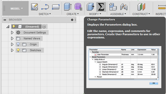
One thing really cool that you can do with parametric software such as fusion360 is to create your own parameters, so I know I will be using carboard for my design, but thickness may vary, so I will set a parameter in my design so I can always change every things that depend on the material thickness. First, I need to open the change parameters function.
Then I add a parameter and give it the condition I want.
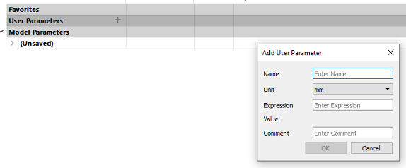
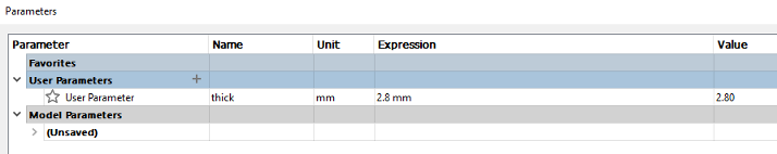
Now, if I ever need to change the thickness of my material, instead of changing every concern dimension in my draw, I can come here and change this parameter.
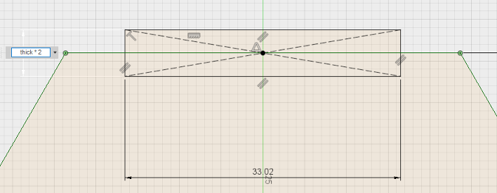
Next, I will draw a rectangle in the midle of one of my side and give it 1.5 inch long / my thickness material * 2,
Now I want to do a circular patern on my rectangle to make a clone of this rectangle on everyside of my hexagone:
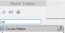
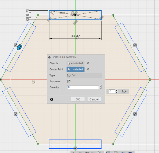
\
Finally, I'm gonna create a second rectangle under the first one that will act as the slot of my pressfit. one the rectangle is drawn, I will again make a circular patern.

All I have left to do is a extrusion, In this extrusion, I only need to select what I actually want to extract, so everything exept the inside part of the first rectangle.
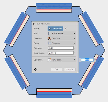
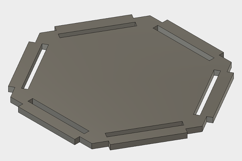
And here we have it, easy peasy!
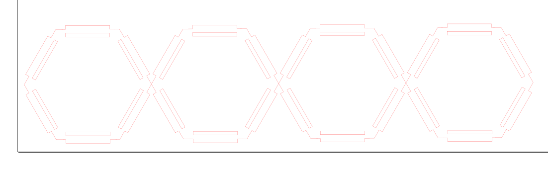
I import my PFD file into Inkscape for getting my gile ready for the laser.
Once in Inkscape I deleted everything from the draw exept the actual design, I set my stroke to a solid red (255,0,0,255) and multply it 4 times.
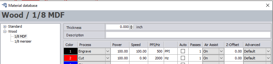
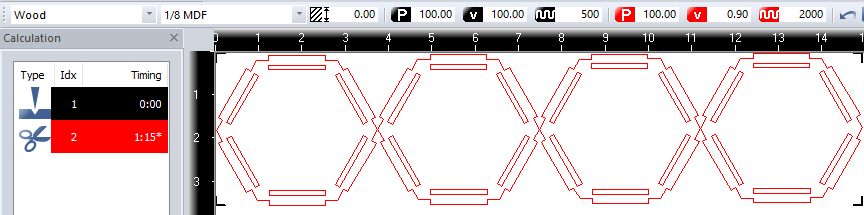
I then "print" the file using my trotec printer, that opens up job control (the software controlling my lasercutter), Inside Job control I set up my laser parameter for cutting 1/8 MDF.
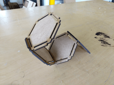
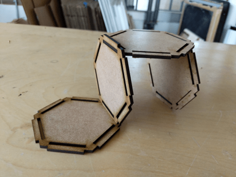
Due to my previous test using my pressfit tool, it fit perfectly on the first try, here are the results!
 Download here!